Draw the Moment Diagram for the Shaft.
Draw the shear and moment diagrams for the shaft and determine the shear. B y2 400 - 9001 0 633.
Solved Draw The Shear And Moment Diagrams For The Shaft The Chegg Com
Draw the shear and moment diagrams for the beam.

. From left to right make cuts before and after each reactionload. Solution Download Draw the shear and moment diagrams for the shaft in. Draw the shear and moment diagrams for the shaft The bearings at A and D exert only vertical reaction on the shaft.
The location at where the shear is equal to zero can Obtained by setting V Oin 1. Assume the support at B is a roller and A and C are fixed. A y 250 - 900 0 B y 250 N M A 0.
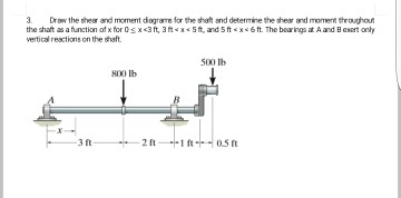
Draw the shear and moment diagrams for the shaft in terms of the parameters shown. Draw the shear and moment diagrams for the shaft and determine the shear and moment throughout the shaft as a function of x for 0 x 3 ft 3 ft x 5 ft and 5 ft x 6 ft. Draw a dot at the end point of.
The FBD of the entire shaft will look like below. Then click on add segment button to add functions between the lines. Draw the shear and moment.
Equations of EquilibriumReferring to the free-body diagram of the shaft shown in Fig. Draw the shear and moment diagrams for the shaft. E 29103 ksi close.
If you inadvertently place two vertical lines at the same place it. Draw a straight line from zero to-50ftlb underneath the support at A. There is a thrust bearing at A and a journal bearing at B.
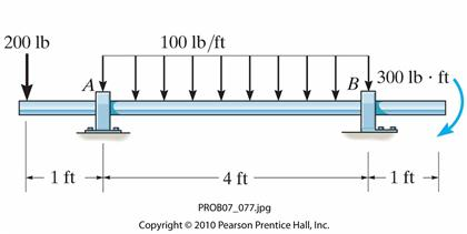
The bearings at A and B exert only vertical reactions on the shaft. How the bending moment diagram of an overhanging beam will be if only we can draw the shear force diagram since it dictates the shape of bending moment. F 200 Ibquad w 100 frac Ib ft quad M 300 Ibftquad a 1 ftquad b 4 ftquad c 1 ft.
Draw the shear and moment diagrams for the shaft. Once you have the reactions draw your Free Body Diagram and Shear Force Diagram underneath the beam. Solution for Determine the moments A B and Cand then draw the moment diagram.
2 kip 2 kip 2 kip 2 kip Kip MKp-ft 61. A 30-mm-diameter solid steel shaft supports loads PA 1300 N and PC 2880 N as shown. L 6 m.
4 kNm 3 m 3 m A B Since the loading is discontinuous at support Bthe shear and moment equations must be written for regions and of the beamThe free-body diagram of the beams segment sectioned through an arbitrary point within these two regions is shown in Figs. Pully Shaft Design Problem. 60 kN 30 kN V- Diagram -36 kN -78 kN 2m 6m 3m.
Finally calculating the moments can be done in the following steps. Note - Make sure you place only one vertical line at places that require a vertical line. Draw the bending-moment diagram for the shaft and then from this diagram sketch the deflection or elastic curve for the shafts centerline.
The details of the input and output torques are shown below. A a Shear and Moment Diagram. Draw the shear and moment diagrams for the shaft.
A M -75x2 1050x - 3200 Ans-200 - 150x - 4 x - 4 2 M 0. KN 10 3 N. Determine the moment at B and the draw the moment diagram.
P 9kN a 2 m L 6. KN 103 N Given. Problem 12 Easy Difficulty.
The value of the moment atx evaluated using Eq. WoL 128 The value of the moment at L 2 is evaluated using either Eqs. There is a thrust bearing at A and a journal bearing at B.
Part B Draw the moment diagram for the shaft. Draw the shear and moment diagrams for the beam. For the bending about y axis.
The shaft is supported by a smooth thrust bearing at A and smooth journal bearing at B. As shown in Figs. F R LA dA w 0 L L 0 sina p L xbdx 2w 0 L p w 0 w w 0 sin x A B w x L 2 p L L 2 The moment of inertia of the cross-section about z and y axes are For the bending about z axis.
The bearings at A and B exert only vertical reactions on the shaft. The bending stress distribution for bending about z and y axes are shown in Fig. Draw the shear and moment diagrams for the shaft in terms of the parameters shown.
The loading is applied to the pulleys at B and C and E. P 9 kN. The shear diagram is plotted using Eqs.
VXN 800 mm 250 mm 75 24 kN. Moment diagrams like shear diagrams begin and end at zero. Draw the shear and moment diagrams for the shaft The bearings at A and D exert only vertical reaction on the shaft.
The supports at A and C are pins and B is a roller. First week only 499. 0 can be The moment diagram is plotted using Eqs.
Also express the shear and moment in the shaft as a function of x within the region 125 mm 6 x 6 725 mm. The bearings at A and B exert only vertical reactions on the shaft. Diameter solid steel shaft supports loads PA 55 Ib Pc 165 lb and PE 45 lb.
The moment in each section is the integral of that section in the shear diagram. Draw the shear and. Lathe MC 40 N-m.
Draw FBD of the entire shaft. Draw the shear and moment diagrams for the shaft. Drilling MC 30 N-m.
Draw the shear and moment diagrams for the shaft. Draw the shear and moment diagrams for the shaft in terms of the parameters shown. KN 103 N Given.
Draw the shear and moment diagrams for the overhang beam. Mechanical Engineering questions and answers. A 2 m.
1- Draw the shear and moment diagrams for the shaft and determine its required diameter to the nearest 18 in. Draw the shear and moment diagrams for the shaftThe hearings at A and B exert only vertical reactions on the shaft. Assume no couples are applied on the beam.
Draw the load and bending moment diagrams of a beam that corresponds to the given shear diagram. Draw the load and bending moment diagrams of a beam that corresponds to the given shear diagram. The bearings at A and D exert only vertical reaction on the shaftThe loading is applied to the pulleys at B and C and E.
Click on add vertical line oft to add discontinuity lines. The area regions of the shear diagram are labeled below and will be referenced further on. Draw the shear and moment diagrams for the overhang beam.
1500 N 800 N 600 mm 125 mm 75 mm Prob. Start your trial now. The area of the first region in the shear diagram is.
There is a thrust bearing at A and a journal bearing at B. To calculate the bending moment of a beam we must work in the same way we did for the Shear Force. Draw the shear and moment diagrams for the beam.
The support at A is a journal bearing and at B it is a thrust bearing. Draw the shear and moment diagrams for the shaft in terms of. Milling MC 20 N-m.
A y 650 N cF y 0. P 9kN a 2 m L 6 m.

Draw The Shear And Moment Diagrams For The Shaft The Bearings At A And D Exert Only Vertical Reaction On The Shaft The Loading Is Applied To The Pulleys At B And C

The Shaft In Fig 6 17 A Is Supported By A Thrust Bearing At A And A Journal Bearing At B Draw The Shear And Moment Diagrams Holooly Com
Draw The Shear And Moment Diagrams For The Shaft If It Is Subjected To The Vertical Loadings Of The Belt Gear And Flywheel The Bearings At A And B Exert Only Vertical
Solved Draw The Shear And Moment Diagrams For The Shaft And Chegg Com


Comments
Post a Comment